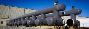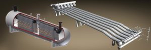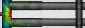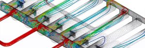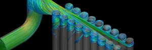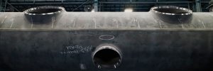
Vortex Tube Design
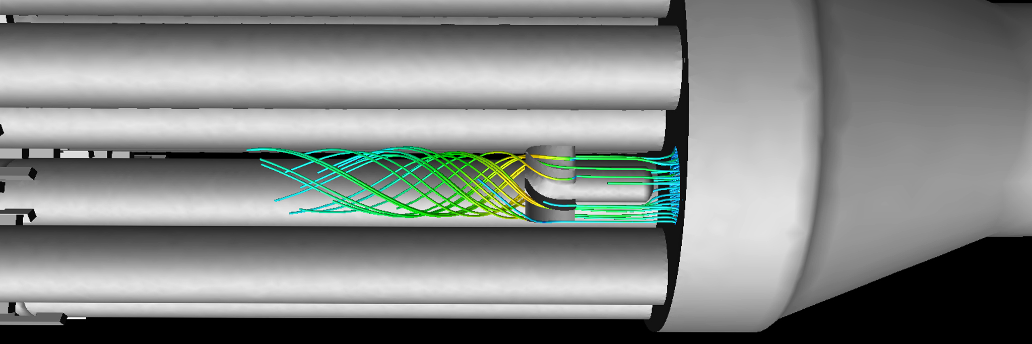
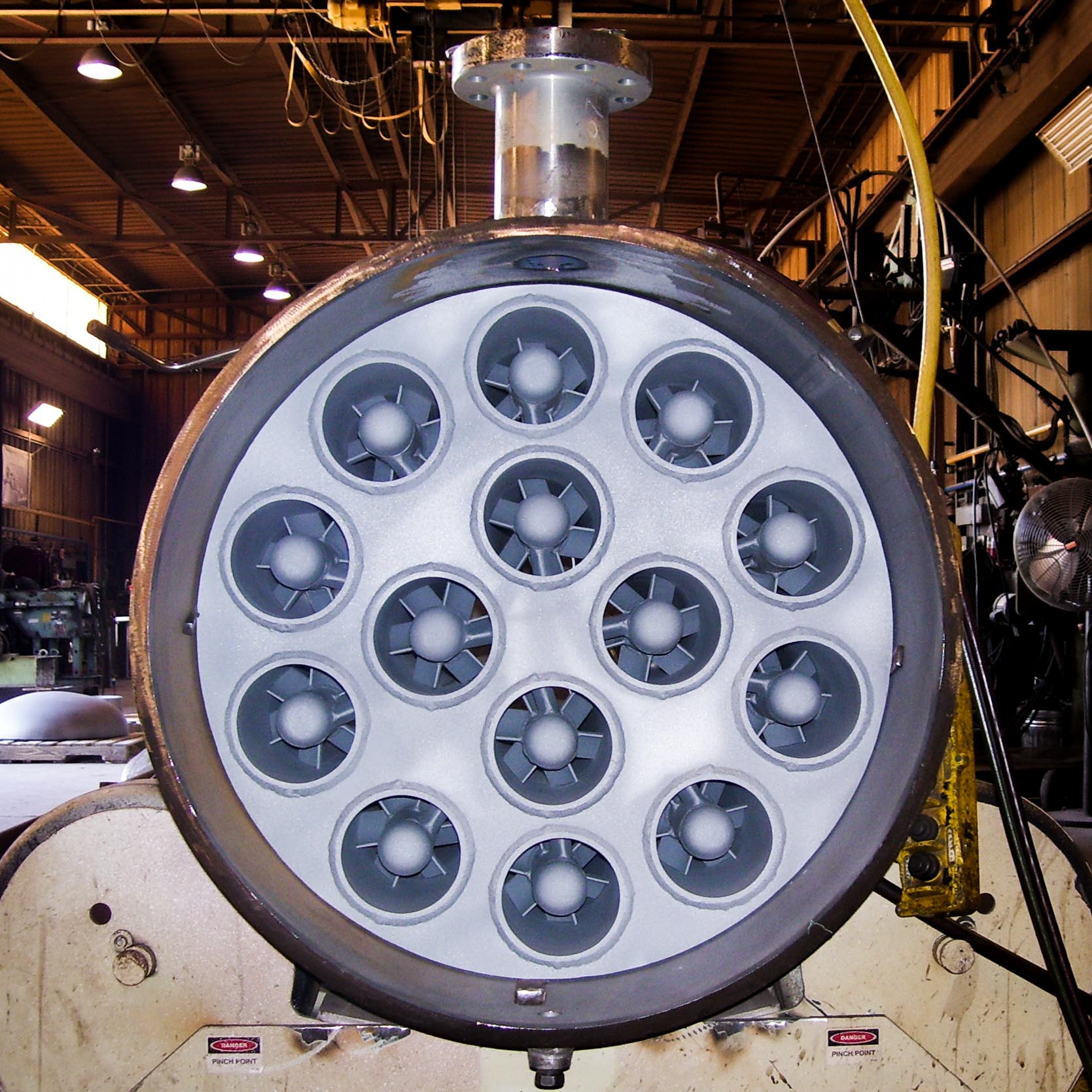
The vortex tube scrubbing system is unique to the cyclonic separation space due to the use definition as a “recycle” type separator. The small 8-10% portion of the gas stream acts as a motive to drive the liquids out of the internal tube via circumferential gap near the back of the tube. The internal centrifuge or tornado is generated by fixed vane entry or Whirly Jig into the internal tubing. The “G” forces generated by the Whirly Jig separates the liquids from the gas. The Whirly Jig’s patented curvature is critical to optimal performance within the tubing. The liquids leaving the gap exit out of the gas outlet while the liquids will drain into a boot or straight to storage tank downstream.

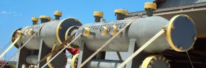
History
The first Vortex Tube Scrubber was patented in 1972 and has since been modified and upgraded into the technology design by Taylor Forge today. Vortex tube designs have been very influential in the development of Vertical and Horizontal 2-phase scrubbers (note: the Vertical Vortex Scrubber does not require platforms or ladders) as well as Vertical and Horizontal Knock Out (K.O.) designs to remove surges or slugs. The maintenance free vortex system reduces the size of the vessel by processing the gas faster than it would in an empty separator vessel. A vortex unit requires no shutdowns (no elements, the Vortex Scrubber operates using steel tubes) while providing effective 2 phase separation.
Pressure Drop
The vortex tube design can operate a variety of different pressure drops. With a fixed vane assembly, the design pressure drop will remain constant through the life of the separator. The designed pressure drop is directly tied to the sizing of the vessel. As an example, a maximum pressure drop of 1psi will result in a much larger vessel than 3 psi. Unlike filters, the 3 psi will not increase over time requiring change out, so often a slightly higher than usual maximum pressure drop is worth considering.
Turndown
The vortex tube design is capable of separation in a wide range of process flows often up to a 10:1 turndown ratio. Unlike conventional separators, the ultimate design constraints of a vortex separator are the low flow case where the tornado is no longer present. Our process engineering team will determine this point on the process curve and begin the design to ensure the unit will work from the lowest to the highest flow provided.
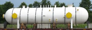
Applications
The Vortex Tube Scrubbers have a wide variety of applications within the oil and gas industry. Commonly found at the inlet to compressor stations, meter skids and stations, throughout gas process facilities, amine treaters, wellhead separators, and other high efficiency applications. Generally, a vortex tube scrubber can be used in any high efficiency application that is currently using a filter separator or coalescer, wire mesh, or vane separator. Unlike many of these designs, there will be no change in pressure drop over the life of the unit and no need for a quick opening closure for regular filter changeouts.
As an example, in scenarios where hydrocarbons are being transported via pipeline to a processing plant, a high efficiency Vortex Tube Scrubber is preferential to protect inlet / outlet compression, or other equipment downstream at a fraction of the size and operational maintenance of competing conventional separation technology. The Vortex Tube Scrubbers offered by Taylor Forge Engineered Systems reach efficiencies of 99.9% removal of solids down to ≥ 0.3 microns and 99.9% removal of free liquids down to ≥ 1micron.
The vortex tube design works best as a scrubber where gas is already relatively dry and high efficiency separation with minimal storage capacity is required. They require little maintenance and achieve similar or better performance than your standard mesh pad, vane pack, and filter options. As such, Vortex Tube separators are the perfect scrubbers in front or behind compressors, dehys., Fuel Gas Scrubbers, etc.
Vortex Tube Separation Applications
- Compressor after scrubbers (capable of handling excessive oil)
- Compressor Inlet Scrubbers (protects surges or slugs)
- Free Water Knockout
- Production Separators
- Flare/Vent Separators
- Overhead Accumulators
- Test Separators
- Slug or Surge Catchers
- Cooler After scrubbers
- Gas Injection
- Flash Treaters
- Steam Separators
- Well Test Separators
Note: What does it take to decide if vortex is right for my application? At Taylor Forge our design considerations are thorough and customizable for each specific job. Before sizing vortex tubes or clusters, we begin with the operating pressure (psig) and gas flow (MMscfd). Fluid composition is also required for adequate design which includes gas, oil, and water compositions, as well as phase characteristics such as mist, foam, and emulsion. Along with calculating the size of the vortex tubes and clusters, obtaining these parameters also assists with our design and placement of the vortex equipment relative to the corresponding liquid interface levels.