There are three prevailing approaches to separation on a finger or harp type slug catcher: Stacked Stoke’s Law Design, Stratification, API 12J Vessel over Fingers. When considering the design for your facility, you need to consider the positives and negatives for each design to determine which will meet your site needs.
Why Separation Method Matters.
Slug catchers remove the bulk liquid from a pipeline as it enters a processing facility. While it’s not expected to provide high efficiency separation, their ability to remove the bulk liquids from the process stream is critical in the function of downstream separators and processing equipment. The particle separation achieved at your slug catcher varies based on the needs of your facility and the type of high efficiency separation you plan for downstream. It’s typical for a finger type slug catcher to separate to anywhere from 50-200 micron. The more effective the separation achieved by your plant’s slug catcher, the more that you can save with smaller separators downstream.
How does Stoke’s Law work?
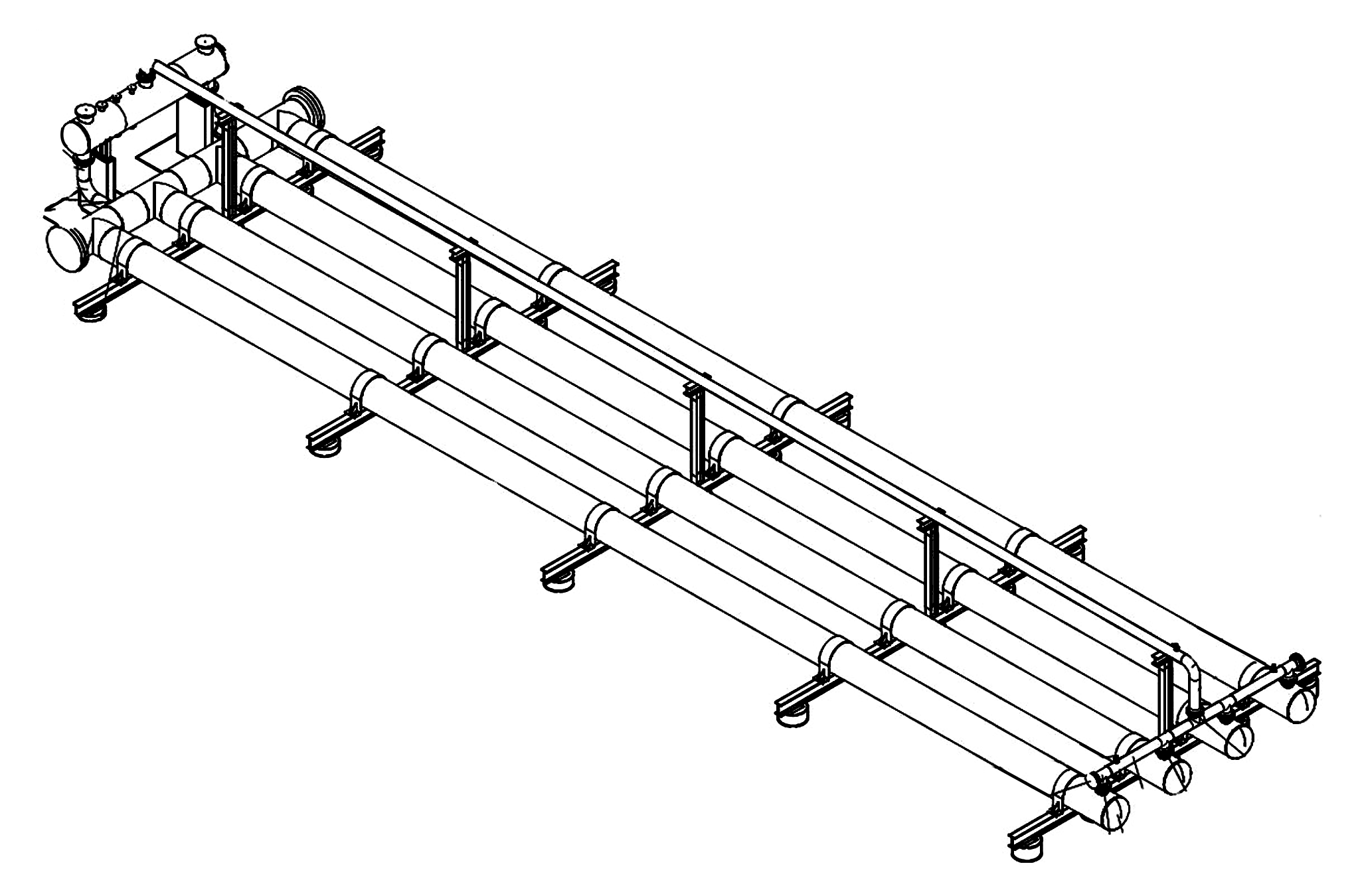
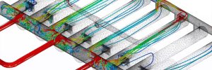
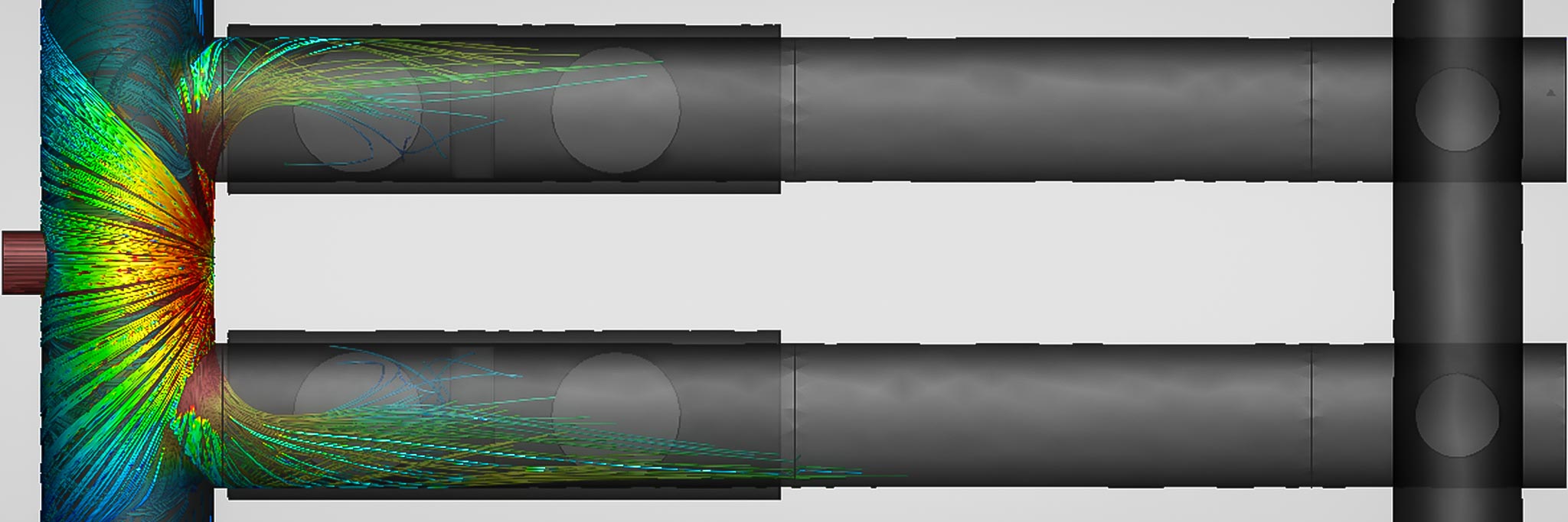
Stoke’s Law as it applies to Separation, applies formulas for momentum, gravity, and viscosity to calculate the distance a liquid particle must travel to fall out from a process stream. In the Taylor Forge design, a downcomer immediately following the main inlet header, removes out all the bulk/free liquids. Only entrained liquid particles remain in the process stream. By calculating the ACFS (actual cubic feet per second) and the gas properties of the stream, the required distance needed for the liquids to drop out can be calculated. The benefit of this design is the bulk separation occurs early in the process. It is very difficult for gas to ‘sweep’ liquids out of the gas outlet because the distance and number of turns (directional changes) all work together to knock out liquid particles. The design has proven significantly more reliable than other methods, especially in upset conditions. For high gas flows, large turndown conditions, and large pigging volume environments, this design emphasizes large manifolds for distribution and downcomers often greater than double competing designs, ensuring performance.

Fabrication
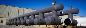
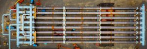
The Taylor Forge stacked slug catcher design utilizes extruded manifolds to achieve uniform mechanical properties across the entire slug catcher unit. The gas inlet, gas outlet, and liquid outlet manifolds will all be shop fabricated and shipped fully assembled to the site. At the site, finger pipe will be welded to the manifolds, as with other designs. Unlike a design utilizing standard tees, pipe, and fittings, extrusions use no additional pipe in the manifolding next to the fittings, leading a smaller footprint, saving significant money during installation. Perhaps most importantly, extruded manifolds are made from proprietary high strength low alloy carbon steel plate. As such, the manifolds can be heat treated to the strength and MDMT properties to fit your environment at no extra cost. For this reason, extrusions are by far the most competitive option in low or high pressure and especially NACE Region 3 critical environments. Additionally, this design will slope 1:100 for the length of the slug catcher. This design will often be many feet shorter than a stratified design with large storage requirement due to the increased slope of the inlet required to stratify the flow. The cost to install higher concrete or steel piers is substantial.
How does Stratification work?
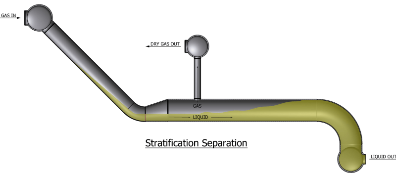
Stratified flow refers to the fluids in a particular process stream being separated into different layers. The lighter density fluids will flow above the heavier density fluids. A slug catcher utilizing stratification uses gravity forces to cause liquid to stratify at the bottom of pipe while the gases exit out the ‘risers’ to the dry gas outlets. The separation is occurring in a concurrent state, meaning the gas and liquids are moving in the same direction. Additionally, the storage portion of the fingers must be oversized by ~20% to ensure your max liquid holdup won’t reach the dry gas riser. This makes the stratified design both longer, wider, and taller than the extruded and stacked design.
At low gas velocity, the interface is smooth or may be rippled by small waves allowing for proper separation. At high enough velocity, droplets can be entrained from the large amplitude, irregular waves and can be deposited at the wall or at the interface. These droplets are unable to escape the gas stream and ‘sweep’ out of the gas riser. Due to the nature of pigging operations, undersized manifolds or risers, and poor inlet design, it can be very common to see high velocity flow. It’s not uncommon for this design to have liquid carryover issues because of the liquid entrainment phenomena.
Fabrication
Shell’s DEP design serves as the common basis for the industry in the absence of the TFES design. This design typically involves utilizing standard tees or fitting and pipe to fabricate fingers with individual ‘risers’ off each finger into a common dry gas header. From an installation and fabrication perspective, this design can be fabricated by most general contractors. This design will be longer and more costly than a Stoke’s Law design because the fingers will need to accommodate full flow with both liquid AND gas. This approach will also be wider when using standard fittings as opposed to extruded manifolds.
How does The API 12J Vessel over Finger Design work?
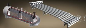
A less common approach is the API 12J Separator Vessel over finger pipe design. In this design the slug surge hits an empty ASME pressure vessel where the gas and liquid separation occurs. The liquids drain out the bottom of the vessel into a set of fingers, while the gas leaves out of the top of the vessel. Like the Stokes law design, the fingers are effectively only storing liquid, so the length is optimized as compared to the Stratified design. This method is simple to calculate and can be built or designed by most engineering or fabrication companies. While two-phase separation is relatively easy to achieve, the problem with this design is the ability to move the slug out of the vessel and into the fingers when pigging. Typically, the downcomers to the fingers are undersized relative to a finger type approach. Its best application is in lower pressure and low gas flow environments where vessels are easily procured, and the separation is relatively minor. Additionally, this design leaves very little flexibility for future gas flow expansion. While common in the US, this design has numerous performance issues. A common design places the fingers above the liquid manifold sloping back towards the vessel. This often causes vapor lock in the unit. It is not uncommon to see very poor distribution and carryover.
Fabrication
The design requires an ASME code shop to build a vessel to sit over the fingers. The typical vessel takes 36-42 weeks to deliver; vessels require longer lead time than the typical harp. The lower sections will be made of either shop or field fabricated headers and line pipe. It should be noted, this design will increase in price significantly the lower the MDMT (anything less than -20°F) or where sour gas is expected (NACE requirements). It is best to fabricate this design in only the smallest and most basic gas plant applications.