Often not a focal point, but many times the downfall of poor designs, distribution is a critical design consideration for finger slug catchers. Equal gas and liquid loading spread among the fingers is key to avoiding carryover. Below are some of the distribution design aspects we recommend considering for your slug catcher design.
Even Distribution
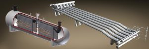
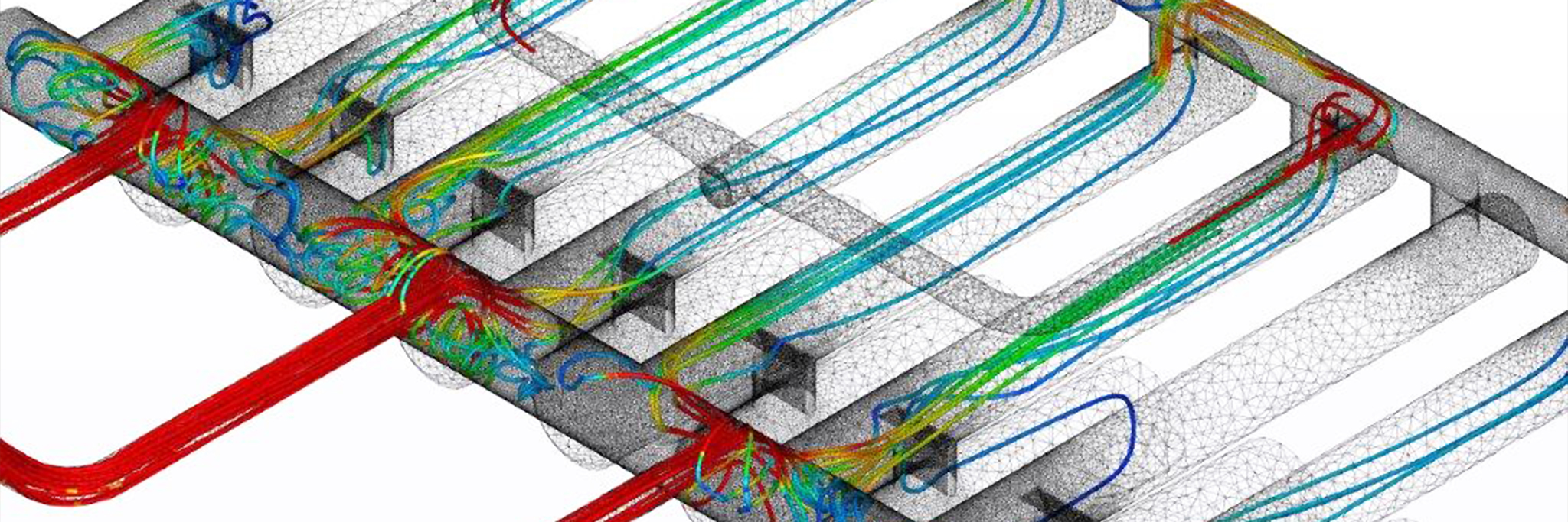
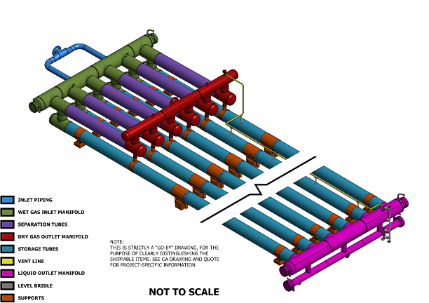
Finger type slug catchers achieve their best separation in even numbers: 4,6,8,10,12 fingers. Odd number slug catchers have a propensity to have uneven distribution; therefore, symmetry is critical. Upset conditions will occur, stratified flow is not always possible, and it’s in these conditions that your slug catcher must be designed to help slow down and equally distribute the flow to avoid flooding fingers. Flooding fingers is a very common issue that leads to flooded vent and balance lines and eventually carryover. This can also be true for a vessel battery in lieu of a harp. When >2 vessels are lined up, proper distribution can be difficult to achieve without proper manifolding like what is a more common practice for Harp designs.
Cross Manifolds
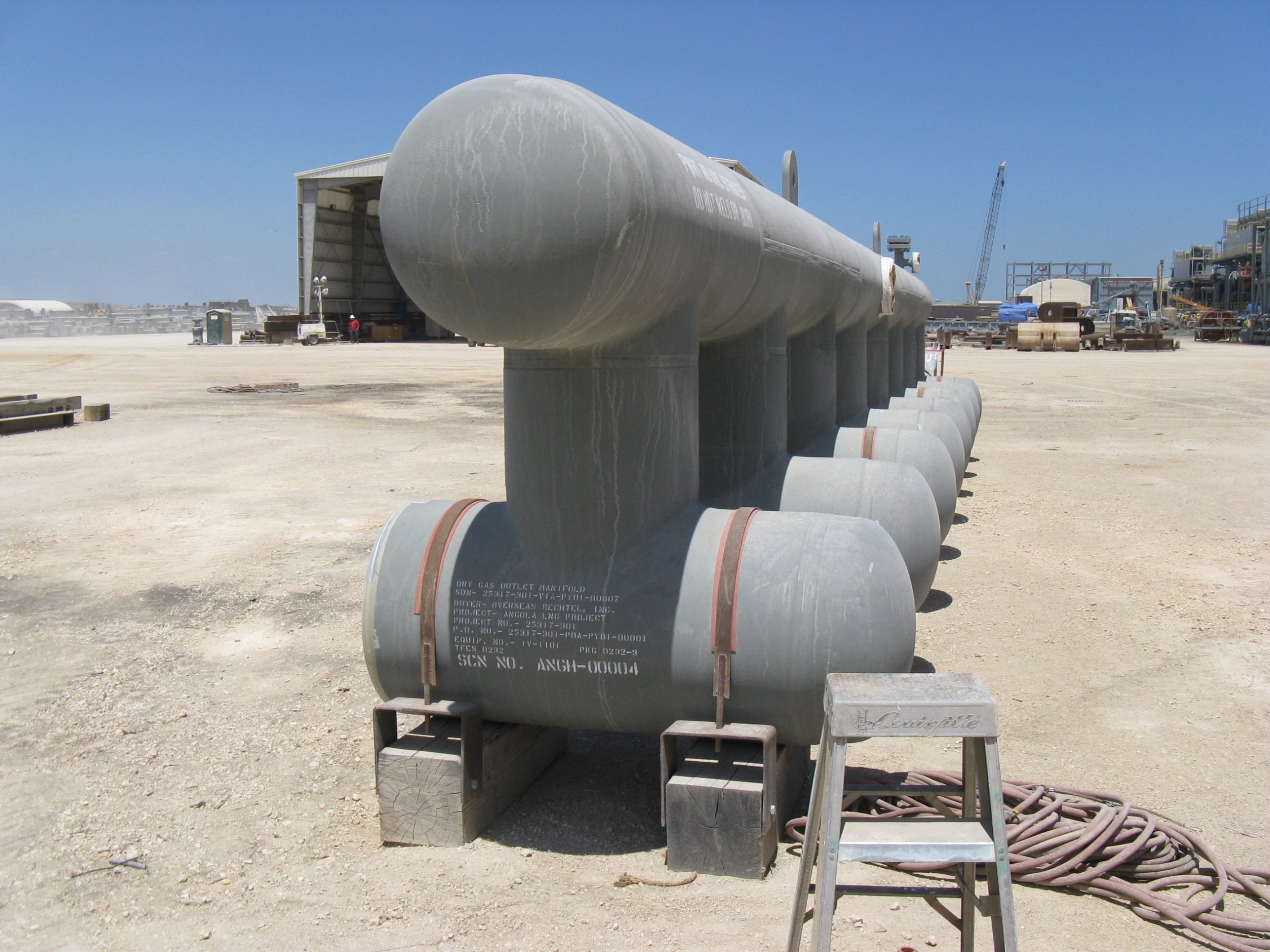
Manifolding is a centerpiece for all Harp designs. They also represent the most expensive part of the design due to the fitting fabrication. Many non-TFES designs seek to shrink their manifold sizes and number of manifolds to lower their cost. This can be extremely detrimental to balancing flows throughout the unit.
We recommend three (3) cross manifolds: wet gas inlet, gas outlet, liquid outlet manifold (and accompanying sludge manifold), to achieve balance across our entire slug catcher. Our cross manifolds can vary in size but never shrink to below 36”ID. This large size allows for more space to slow the process stream and allows for separation. That means we utilize a full-sized header to balance our flows at the inlet and both outlets (gas and liquid). Not just a 10” equalization line in lieu of a liquid manifold. In upset conditions (a pigging event), if flooding occurs, that 10” line will also flood, rendering it incapable of serving its purpose. Without a cross manifold, the fluids have no way of balancing and will then carry over out of your gas outlet.
The cross manifolds balance the liquids at both the inlet and outlet. If an upset condition causes one finger to receive more liquids, the back end of the slug catcher will redistribute the flow in the fingers preventing the liquid from backing up into the separation section of the slug catcher.
5D Inlets and Outlets
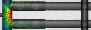
It is both our recommendation and industry standard to include a minimum of five (5) diameter lengths of straight pipe run prior to entering the slug catcher. This simple but imperative design note helps the unit achieve laminar and stratified flow entering the slug catcher. The smooth flow better ensures even distribution at the inlet of the fingers. It also allows the liquid to have some time to slow prior to entering the unit
Downcomers
A finger slug catcher’s primary goal is to separate bulk liquids from the process stream. To accomplish this, all designs use some form of a riser or downcomer to separate bulk liquid away from the gas. We’ve found an undersized downcomer or riser can quickly form a choke point in the slug catcher’s system and lead to significant carryover.
Our design utilizes the downcomer for both liquid separation to the fingers and also vapor return up to the gas outlet. We size our downcomer to handle the volume at a worst-case scenario (highest possible ACFS from the conditions given) to prevent choking. We do not consider a reduced pigging flow rate. We expect our design to perform at 100% gas flow rate at the lowest operating pressure and highest temperature. Please contact us for more explanation.