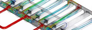
Vortex Cluster Design
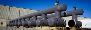
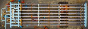
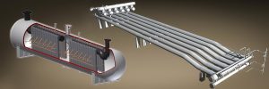
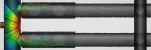
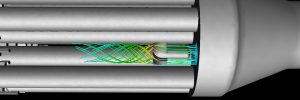
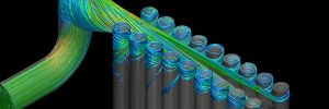
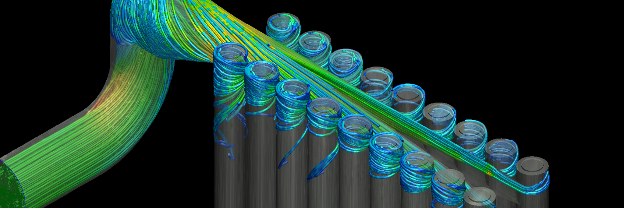
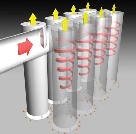
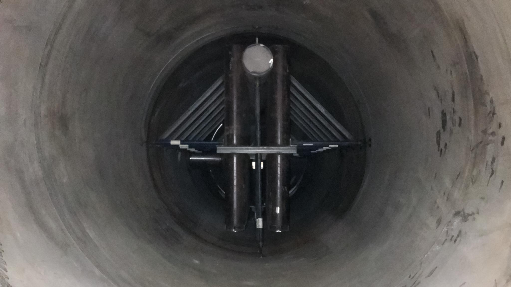
The vortex cluster is a unique technology within the cyclonic separation space. Utilizing an internal piping system with internal baffling and large tangential entry, the system is both very low pressure, capable of handling large liquid slugs and surges and solids, while also separating at a very high efficiencies seen typically in scrubber and filter technology. An internal piping system ensures the incoming process stream maintains proper velocity entering the baffle system within the piping. The divider baffle plate ensure liquids and gas are proportionately distributed amongst the “cluster” tubes within the system. As the stream nears entry into the tubes an orifice place on the top of the tubes prevents liquid from. The stream enters tangentially into the vertical tubes which creates a “G” force to compress the liquids on the wall and squeezes the gas from the liquid. During 3-phase separation the difference in liquid densities separates the liquids. Vortex technology also utilizes the vessel fluid levels to allow for coalescing of liquids in 3 phase separation which when combined with the liquid / liquid separation in the Vortex, provides superior liquid / liquid separation efficiency. The liquids leave out the base of the tube cluster tubes, while the gas leaves vertically out of the top through the low-pressure tornado core.
History
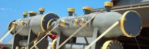
The first Vortex Cluster Separator was installed by ConocoPhillips at their refinery in Dubai, U.A.E, and was designed to stop foaming in a gas / oil separator. The Vortex Cluster has since been very influential in the development of 2-phase and 3-phase separation, and Slug Catchers. Unlike the Vortex Tube design which can flood during large ‘slugs’, Vortex Cluster has been successfully developed and implemented for handling these large flows while also processing gas. By increasing throughput efficiency and decreasing residence time vortex is capable of drastically reducing the size of otherwise conventional separation vessels and systems. In retrofit applications, Taylor Forge can fabricate vortex internals to install in the existing vessel to increase efficiencies and handle increased production without the need for additional equipment.
Pressure Drop
The vortex cluster operates at very low pressure drop typically around 1psi. Over the lifecycle of the unit, there should not be a change to this performance.
Turndown
As with all cyclonic or vortex technology, g-forces drive the separation tornado. As such, the minimum flow the unit will see drives the design as much as the top end flow. With this approach, we can approach 10:1 turndown within our units.
Applications
The vortex cluster design can operate efficiently in a wide array of scenarios. The greatest performance advantage is seen in slugging or high liquid applications where a unit sees high gas and liquid flows. The high velocity cyclones reduce the retention time needed for typical separation shrinking vessel size as compared to empty vessels, vane or wire mesh designs. Applications are also identified when they include any combination of 2 or 3 phase separation, high pressure differentials (Vortex Cluster will reduce or stop foaming), presence of wax or paraffins and large operational ranges. In many process streams with the presence of solids and liquids, the cluster configuration can replace the performance of two vessels. Where typically an operator requires an empty “knockout” vessel followed by some version of higher efficiency separation, the cluster can service both functions. In some cases, a 3-phase design can save a 3rd vessel within the arrangement. The Vortex Cluster systems offered by Taylor Forge Engineered Systems reach efficiencies of 99.9% removal of solids down to ≥ 0.3 microns and 99.9% removal of free liquids down to ≥ 1-10 microns.
Vortex Cluster or Cyclonic Separation Applications
- Emulsion Treaters
- Free Water Knockout
- Production Separators
- Flare/Vent Separators
- Overhead Accumulators
- Test Separators
- Slug Catchers (2 or 3-phase)
- Cooler After scrubbers
- Gas Injection
- Compressor after scrubbers (capable of handling excessive oil)
- Compressor Inlet Scrubbers (protects surges or slugs)
- Flash Treaters
- Steam Separators
- Well Test Separators
Note: What does it take to decide if vortex is right for my application? At Taylor Forge our design considerations are thorough and customizable for each specific job. Before sizing vortex tubes or clusters, we begin with the operating pressure (psig) and gas flow (MMscfd). Fluid composition is also required for adequate design which includes gas, oil, and water compositions, as well as phase characteristics such as mist, foam, and emulsion. Along with calculating the size of the vortex tubes and clusters, obtaining these parameters also assists with our design and placement of the vortex equipment relative to the corresponding liquid interface levels.