Finger style slug catchers work best when receiving and storing large volumes of hydrocarbon slugs, typically from pigging, with high gas flow rates. When optimizing for the most cost-effective design for your site, the points below should help define your approach.
1. Design Codes
Finger type slug catchers are typically designed to a gas transmission code like ASME B31.8 or CSA Z662 in Canada. In rare cases, the slug catcher is located “inside the fence” of a gas processing plant which then requires the use of B31.3 design code. Since B31.3 uses a lower allowable stress calculation for thicknesses and is a minimum wall code, you’ll find that a finger type slug catcher design is approximately 15-25% more costly than B31.8.
2. Gas Flow Rate
The design case for your slug catcher should be based on the highest established actual cubic feet per second (ACFS). This occurs at your highest gas flow rate with coinciding lowest operating pressure and highest temperature. We assume you will pig your line at these maximum conditions. This volumetric flow rate sets the number of fingers you need to process incoming process stream. The storage capacity of the slug catcher will only determine the length of your fingers after you’ve set the width/number of fingers.
3. Symmetry & Distribution
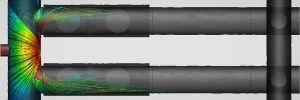
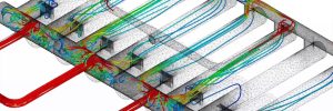
Our extensive experience in the slug catcher business has taught us that symmetry is critical in slug catcher design. To ensure balanced flow among your fingers, utilizing an even number of fingers dramatically improves the reliability of your unit. Additionally, providing 5D inlet piping helps to provide stratified flow so the initial distribution to your fingers is uniform. It is also critical to utilize multiple inlets into your wet gas manifold to properly distribute and slow the flow down prior to entering the separation sections. One of the most common causes of carryover is the flooding of a single finger. We’ve found this occurs most often when you have an odd number of fingers. The other common cause is under sizing the downcomers for bulk liquid separation. When the volume of the downcomer is such that it can’t handle the pigging flow, carryover is more likely to occur.
4. Plot Space
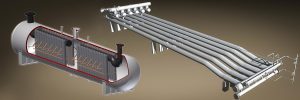
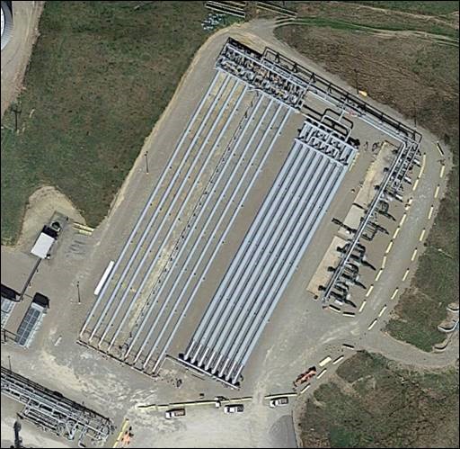
Available plot space can have a sizable impact on the price of your slug catcher. A long and skinny finger-type slug catcher is going to be your most economical design. You’ll need to evaluate the plot space vs. the liquid hold-up requirements to determine the best design. Pipe is cheaper than manifolds (see choosing a slug catcher section for some rule of thumb pricing), so minimizing fingers by making the unit longer (when the gas flow allows) will achieve superior economics. The slug catchers to the right have nearly identical performance, however, the Taylor Forge extruded manifold design saves significant space.
It should also be noted that the Stratified design employed by the Shell DEP specification and used throughout the US by other vendors, will be wider, taller, and longer than the Taylor Forge approach. This cost is often hidden in the installation of the slug catcher. The stratified design requires a nearly 7:100 slope compared to the 1:100 by Taylor Forge. This elevates the unit anywhere from a couple to 15’ higher in the air. Making installation more difficult and foundations drastically more expensive.
5. Material Selection
When the presence of CO2 or H2S is not within a process stream, high strength carbon steel fittings designed to MSS-SP-75 will be sufficient. The NACE service region will help guide when alloy materials or testing are required. As CO2 or H2S percentages increase, especially with the presence of water, carbonic and sulfuric acid can form a corrosive environment. The determination of NACE region involves a partial pressure calculation (Annex C & D) of H2S and CO2. Additional testing (hardness, contaminants, etc) or a CRA (corrosion resistant alloy) may need to be considered. We’ve fabricated slug catchers utilizing Stainless Steel and Inconel CRA used in these extremely sour cases. For the line pipe, API 5L strongly guides the end user is chosen to apply Annex H and K which requires HIC testing of the line pipe plate.
6. Process Conditions
The operating pressures, flows, and gas properties are required to design a finger type slug catcher. You can find a data sheet on our website. Below are the most important properties and how they affect the design.
- Design pressure – sets the thickness of your pipe and manifolds. Higher pressure = higher cost
- Operating pressure – as pressure increases the slug catcher shrinks because gas is compressible
- Gas flow – the gas flow helps define the volume of gas the slug catcher will need to separate and at what velocity – defines the number of fingers needed
- Liquid storage or holdup – defines the length of your fingers
- Gas composition – required for micron separation calculations
- Particle separation needs
7. MDMT
High strength fittings, as a standard, are designed to -20°F. That’s typically what you’ll find in stock for tees. Extruded manifolds are much more diverse. At no extra cost, an extruded outlet can be designed to -50°F. It should be noted that the API 5L pipe will require some extra testing for any temperatures below -20°F.
8. Future Expansion
Expanding a finger type slug catcher can be tricky. While adding additional liquid storage is not an issue, adding gas processing for increased gas flow can be very difficult once the number of fingers is set. For this reason, we recommend designing your slug catcher for the lowest operating pressure you expect to see from your producers at coinciding high gas flow. If this design philosophy is utilized, it can be quite easy to add additional fingers to your slug catcher later to handle additional storage/holdup.
9. Finger Type Slug Catcher Process Design Guarantee
To hold your vendor accountable, a process design guarantee needs to be provided. The guarantee should be based on the micron separation the finger type slug catcher will achieve at your worst-case scenario. Most of the time the worst case scenario is during your site’s pigging event. It is wise to ask the vendor to size of the 100% gas flow rate at the lowest expected operating pressure and highest temperature. This is the highest actual cubic feet per second (ACFS) seen by the pipeline. It is common for other vendors to ask for the pigging flow rate, this requires an assumption and often leads to under sizing the slug catcher and/or making it difficult to bring additional gas flow into the slug catcher later.
In all cases you should accept no less than 200 micron from your vendor. The industry standard is 150 micron. 300-500 micron guarantees are an easy way for stratified and vessel designs to shrink their manifolds and vessels to be more competitive with the Taylor Forge approach.